5 Facts About Computer Scanners
- The history of Computer scanners began when Rudolf Hell came up with the idea for the fax machine about 50 years ago. The scanner was then invented in Kiel, starting with the fax machine. The first image it scanned was of Walden, the son of the inventor of computers scanner.
- If you scan a document, you can keep a copy on your laptop or computer and have it with you at all times. Scanners also help cut down on the amount of paper that is used. You can take a picture of the document and make many copies of it to pass it around.
- The scanners help to speed up the process and work of the office. In addition, it enables you to keep your documents safe by converting them into a digital form so that you can save them on your computer or send them to someone else by email or text message.
- While the first scanners could only read 8 bits (28), then 10 bits (210), then 12 bits (212), they can now read up to 16 bits (216), or 65,000 greyscales. However, the human eye can’t see all of them. But, with time, scanners have grown in cost too.
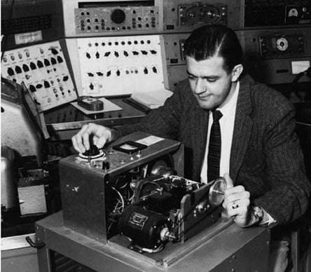
- The first scanner developed for use with a computer, was a drum scanner. It was built in 1957 at the US National Bureau of Standards by a team led by Russell A. Kirsch, working on America’s first internally programmable (stored-program) computer, the Standards Eastern Automatic Computer (SEAC), in order to enable Kirsch’s group to experiment with algorithms that launched the fields of image processing and image pattern recognition.
Computer Scanner: History
In the world of computers, the scanner is a device that optically scans images, printed or written text, a three-dimensional object, etc. representing it in a digital format.
The now ubiquitous device can be found in offices as a desktop (or flatbed) scanner, where the document is placed on a glass window for scanning; in engineering and creative labs as a 3D scanner, used for industrial design, reverse engineering, test and measurement, gaming and other applications; in printing shops as a very-high-quality drum scanners, that are superior in resolution, color gradation, and value structure.
The modern scanner may be considered the successor of early fax and telephotography input devices from the 19th century.
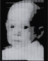
A drum scanner was the first picture scanner designed for use with a computer. A team led by Russell Kirsch was the inventor of the first computer scanner. A 5 cm square photograph of Kirsch’s three-month-old son, Walden, was the first image scanned on this scanner.
Drum scanner could send documents in the form of an image rasterized into lines and pixels.
For the first time, this machine could read color originals optoelectronically, which means that it could convert color values into electrical current. In addition, this machine had a sensing drum. A photomultiplier used “light sensors” to turn incoming light into electric current. It then increased the voltage, so it could reach a high-density range.
The “flatbed scanner” came from this expensive, complicated device. It used a different, more cost-effective technology, the CCD element, to make a “scan line” that used a series of color-sensitive photodiodes to read an image and make it look like it did in color.
The scanners kept getting better because so many different jobs needed to be done. For example, there were variations of the flatbed scanner for other formats, camera scanners with free-moving lenses for three-dimensional objects, and film scanners for negatives and slides, to name a few.
They then changed the CCD line to the CCD chip (the Bayer chip), which can read an entire color document in a split second by reading out the RGB-Bayer matrix.
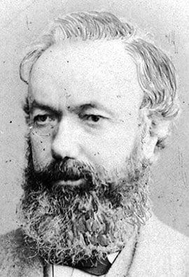
The first “fax” device was developed in the early 1840s by the Scottish inventor Alexander Bain (1811–1877), who is primarily known as the inventor of the first electric clock in 1841. On 27 May, 1843, Bain received a British patent (№9745) for improvements in producing and regulating electric currents and improvements in timepieces and in electric printing and signal telegraphs, and later made some improvements in his next patent (№10838), granted on 25 September 1845.
Bain began inventing in the 1830s, developing inkstands, ink holders, a ship’s log and later many electrical devices, including various types of automatic telegraph, an electric clock, an earth battery, insulation for electric cables and an electric fire alarm for the army.
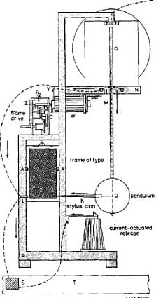
In his experimental facsimile apparatus from 1843 (see the nearby drawing), using his experience as a clockmaker, Bain used a clock to synchronize the movement of two pendulums for line-by-line scanning of a message. As a reading/writing device he used a stylus that was an electrically conductive swinging pendulum. As the pendulum swung back and forth across a raised image on a copper plate, electrical pulses are generated. Besides that, each swing of the pendulum moved the copper plate to a small step so that the pendulum was able to scan entire plate surface.
The electrical pulses were then sent across five wires to a receiving device, that also featured a pendulum. Its pendulum was synchronized with the sending device pendulum, which allowed the receiving side to generate an exact replica of the original image, using electrochemically sensitive paper impregnated with a chemical solution of ammonium nitrate and potassium ferrocyanide.
In his patent description, Bain claimed that a copy of any other surface composed of conducting and non-conducting materials can be taken by these means, but actually his mechanism reproduced poor quality images and was not a viable device mainly because the transmitter and receiver were never truly synchronized.
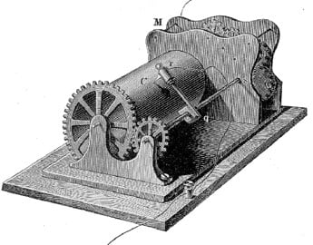
Bain’s concept of the fax was somewhat improved in 1848 (British patent 12352) by the English physicist Frederick Bakewell (1800–1869), but Bakewell’s device (see the lower patent drawing) also reproduced poor quality images.
By the late 1950s digital computers were in common use in many laboratories and commercial establishments. Originally, they were devoted exclusively to numerical, algebraic, and geometric computation. Later, the symbol manipulation capability of computers became recognized, leading to so-called business data processing in which alphanumeric processing became routine. The alphanumeric data presented an obvious problem of inputting the vast quantity of data needed for business. This created activity in developing character recognition machinery.
It occurred to Russel Kirsch that a general purpose computer could be used to simulate the many character recognition logics that were being proposed for construction in hardware. This would require an input device that could transform an image into a form suitable for storage in the memory of a computer. Voilà, the scanner was born.
The SEAC scanner used a rotating drum and a photomultiplier to sense reflections from a small image mounted on the drum. A mask interposed between the picture and the photomultiplier tessellated the image into discrete pixels.
The first image ever scanned (see the nearby image) on the scanner was a 5×5 cm photograph of Kirsch’s then-three-month-old son, Walden. The black and white image had a resolution of 176 pixels on a side.
A further important advantage of building such a device was that it would enable programs to be written to simulate the various ways in which humans view the visible world. A tradition had been building in which simple models of human structure and function had been studied, for example, in neuroanatomy and neurophysiology. The emphasis on binary representations of neural functions led us to believe that binary representations of images would be suitable for computer input. This serious mistake was implemented in the first image scanner built.
A serial-parallel converter (staticizer) was connected to the SEAC memory, enabling a stored image to be displayed on a cathode ray oscilloscope, thus making it possible for the researchers to see what the computer saw. And when they could see binary images, they realized the limitations of binary representation. So they experimented with superimposing multiple scans at different scanning thresholds and the use of time varying thresholds for pulse density modulation to represent multiple gray levels in an image.
Computer Scanner: How It Worked?
Drum scanners take very detailed pictures. They use a piece of technology called a photomultiplier tube to make things look better (PMT). In PMT, the paper to be scanned is put on a glass cylinder. It has a sensor at its center that turns the light from the document into three separate beams, so it can be seen. Each beam is sent through a color filter and turned into an electric signal in a photomultiplier tube.
The main idea is to look at an image and do something with it. For example, it’s possible to save images and text to a file on your computer with tools called “optical character recognition,” or OCR. You can then change or improve the picture, print it out, or use it on your Web page.
The drum scanner works by putting a film or print image on the outside of a clear glass cylinder and sticking it to the machine. The drum is turned on, which causes it to spin at high speed. A light source inside the cylinder sends out a focused beam of light that passes through the glass cylinder and the film.
The film on it changes the color and intensity of this light beam. This light then shines on a photomultiplier tube, making it brighter. Like the old-fashioned radio and TV glass tubes, a photomultiplier tube is retro. This tube turns light energy into an electric charge when light hits it. The photomultiplier is excellent because it is able to respond to small changes in light intensity by putting out a signal that is more powerful than usual.
Computer Scanner: Historical Significance
As discussed, the inventor of the first computer scanner was Russel Kirsch, and the first image printed was of his son Walden. However, the computer scanner device has developed into numerous types over time.
Flatbed Scanner
Some people call a flatbed scanner “reflective” because it works by shining white light on the item to be scanned and reading the intensity and color of light reflected from it, usually one line at a time. Some of them have transparency adapters, which aren’t very good for scanning film for several reasons. They’re meant to be used with prints or other flat, opaque materials.
Film Scanner
These types of scanners have great significance today. They are called slide or transparency scans, and they work by shining a narrow beam of light through the film and reading how much brightness or color comes out. Stepper motors move a carrier through a lens and a CCD sensor inside the scanner. Uncut film strips of up to six frames, or four mounted slides, are usually placed in this carrier and moved by this motor. Some models are mainly used for scans of the same size. In terms of both price and quality, film scanners can be very different from one to the next. However, most dedicated film scanners can be bought for less than $50, and they might be enough for small jobs.
CIS Scanner
Contact Imaging Sensor (CIS) is the other way to scan. It doesn’t use a standard lens to put the original image on the sensor. Instead, it uses a lot of fiber optic lenses to send the original image information across many sensors. When it comes to scanning aerial photos or maps, CIS technology is cheaper than traditional CCD models, but there can be some trade-offs for the quality of the scans.
CIS Scanning Technology has a sensor array that scans for things. Keeping a CIS-based system up and running takes less time and money because there are no cameras, and the sensors are controlled by software.
Even though there isn’t as much field depth as other cameras, fold lines and wrinkles will show up with CIS. Because of the way CIS works, there is also less information about color space.
However, consider that the physical CIS technology has some limitations. Many manufacturers have been able to get around this by using sophisticated software that compensates for the CIS shortcomings.
Handheld Scanner
A handheld scanner is an electrical device that scans paper documents and converts them to digital representations. This can be digitally stored, modified, transmitted, or emailed within the digital network.
Specific reading devices are necessary to capture barcodes and access the information behind the codes for further data processing. For example, the handheld scanner can read barcodes and detect code patterns with red or infrared light.
A reading unit and a downstream decoding unit make up the handheld scanner. In practically all device types, the decoding unit is integrated with the reading unit, and it is primarily utilized in retail, logistics, and industrial.
Sheetfed Scanner
A sheetfed scanner (also known as an automatic document scanner or ADF scanner) is a digital imaging system designed specifically for scanning loose sheets of paper. Businesses commonly use them to scan office documents and are used less frequently by archives and libraries to scan disbound books or other robust unbound documents. Sheetfed scanners can be compared based on the paperweight and size they can handle, their duty cycle rating, their speed (pages per minute), and their duplex capability.
3d Scanner
The 3D scanner is one of the most innovative devices invented. However, there are still a lot of restrictions on the types of things that can be scanned. For example, optical technology may have a hard time with dark, shiny, reflective, or transparent objects. For example, industrial computed tomography scanners, structured-light 3D scanners, LiDAR, and Time of Flight 3D scanners can be used to make digital 3D models without destroying the object.
Collected 3D data can be used for many different things. These devices are used a lot by the entertainment industry to make movies and video games, and virtual reality. These are just a few examples of how this technology can be used. Augmented reality and motion capture are two of the most common, but there are many other ways this technology can be used.