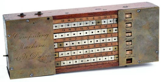
Alexander Davies was a former clerk and accountant who invented a slide bar adder. The device worked by using a carry mechanism which was implemented by a pawl or sliding bolt that was activated when a wheel passed the number nine. It had rows of figures which counted from the top downwards as units of tens, hundreds, thousands, and tens of thousands. Davies received a patent for his invention in 1867. The device still exists today in the National Museum of American History.
Who Was Alexander Davies?
Alexander W. Davies (b. around 1837—died on March 14, 1900) lived in Cleveland, Ohio, where he worked as a clerk, car agent, and accountant for several railroad companies between 1863 and 1900.
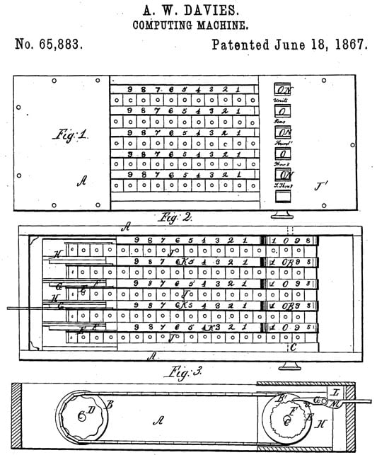
On 18 June, 1867, Alexander Davies from Cleveland, Ohio, received a U.S. Patent 65883 for a slide bar adder, similar to the adding device of George Fowler, patented in 1863. The patent model of the device survived to our time and is kept now in the collection of National Museum of American History in Washington, D.C. He was a holder of two other US patents (US455197 and US456650) for inventions relating to recording the mileage travelled by railroad cars (car mileage register and report).
Davies’ Adding Machine

Alexander Davies’ adding machine is a metal, wood and paper instrument with overall measurements: 4 cm x 21 cm x 8.7 cm.
The device has five continuous endless chains (metal bands), thus corresponding with the rows of figures on the board, which are counted from the top downwards, as units, tens, hundreds, thousands, and tens of thousands, as indicated by the lettering between the opening in the right section of the cover or stop-plate J’.
How Did It Work?

The chains move in slots across a wooden frame, passing around the wheels and B’. Flat pieces of brass cover the top of the frame on the right and the left, keeping the bands in their slots. The chains (bands) are made up of small flat squares of metal, with nine squares silver-colored and the tenth one brass. Each square has a hole at the center for inserting a peg.
Strips of paper attached between the bands are numbered from 1 to 9. Moving a band to the right turns the corresponding wheel clockwise. The edge of this wheel, which is covered around the edge with a paper marked with the digits from 0 to 9, is visible through a window in the right piece of brass. The number shown increases as the wheel turns. A lever on the left side disengages (resets) the fourth and fifth columns.
The carry mechanism, activated when a wheel passes 9, was implemented by a pawl (marked with on the patent drawing), attached to a cam (marked with ), which engages in the notches of the wheel next in order, causing this wheel to move the distance of one link, adding one to the higher position.